One of the problems with running a lot of equipment day and night is the power consumption and the cost attached. To mitigate this I wanted to produce my own power.
I set my budget for the project to be around 1500 euros at first, but in the end it was closer to 1800 euro because it was my first time building a system like this and I encountered some issues along the way. but even still I should recuperate the total cost in about 6-8 years at the most.
Solar panels
The solar panels I used are 4 boviet 275wat panels for about 90 euro each.

The solar panels are set in an east-west facing orientation, this reduces the maximum amount of power you can generate but unless you can store all the excess power some of it will be lost. the advantage of the east-west facing setup is that the power curve is more flattened out.

Since it is a split system with 2 pairs of solar panels that will see a different amount of sunlight it is recommended to use 2 controllers. But using 1 is only a small loss in efficiency because the power point is around the same voltage for most levels of irradiance. only at low irradiance level will the optimal voltage drop. more information can be found in the below paper about the topic that I also used as a source.
Charge controler
The next important item is a good solar charge controller. I went with a 30A MPPT controller from epever (Tracer3210AN). with a 24V battery and inverter, it gives a capacity of 750-800w depending on the state of charge of the battery.
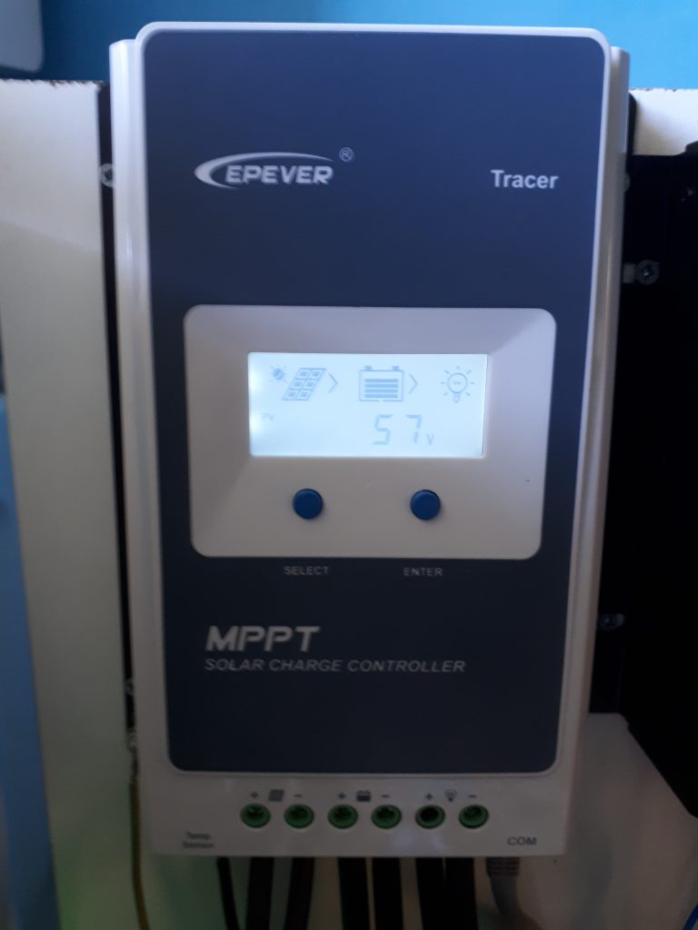
the voltage output regulation is currently still a small issue when there is too much power produced.
I had it configured to charge the batteries to 28.5V and to disable the output when the voltage would rise above 29V. Despite this the voltage would spike sometimes when the battery was almost charged. This would trip the overvoltage safety of the inverter disabling its output. and because there still voltage on the input on the inverter, the transfer switch that switches between main power and inverter power would not switch over to mains power. thus causing a power loss for everything.
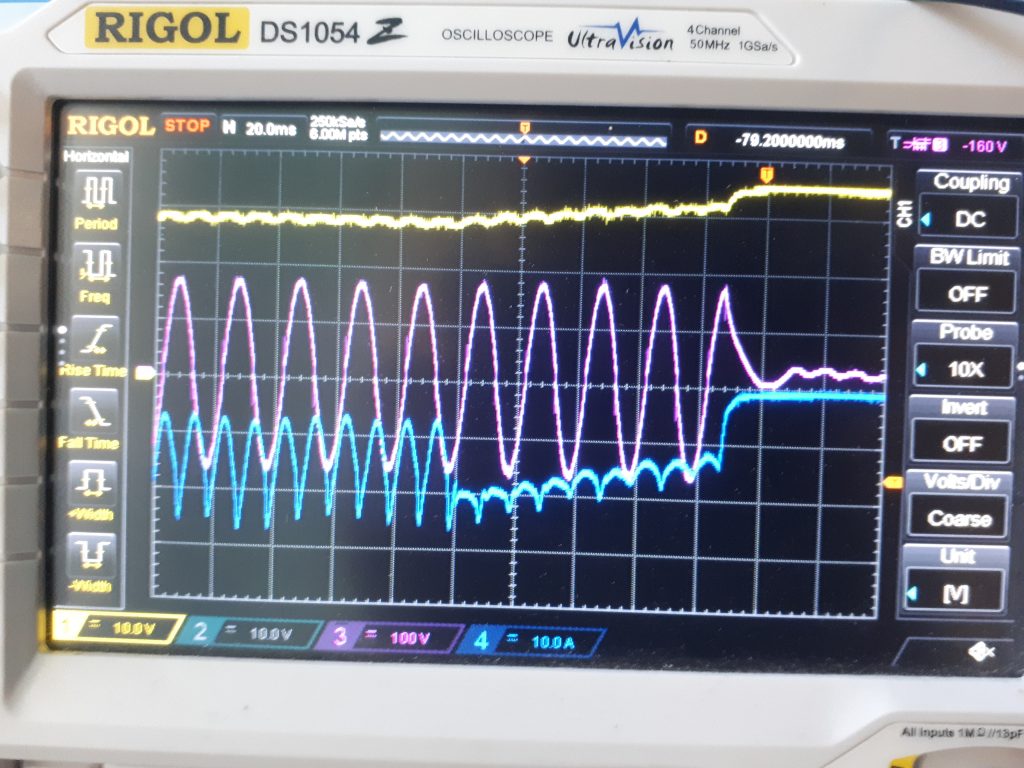
What I suspect to happens is that when the current draw increases suddenly the charge controller overcompensates a bit and makes the voltage rise just above 30V.
when the inverter shuts down and the current disappears the charge controller spikes the voltage to 35V and does not disable its output despite being configured to disable it when above 29! not only that but it takes a good second the settle back down.
It took me a while to figure this out since it only happened when the batteries were almost fully charged and even then it could take up to an hour for the fault to occur. I tried to the fault occur deliberately by causing big power spikes and dips when the batteries were full but could never recreate it. So I set my oscilloscope to trigger when the power goes out and after 2 days waiting there was finally enough sun to charge the batteries and the fault finally occurred.
Battery
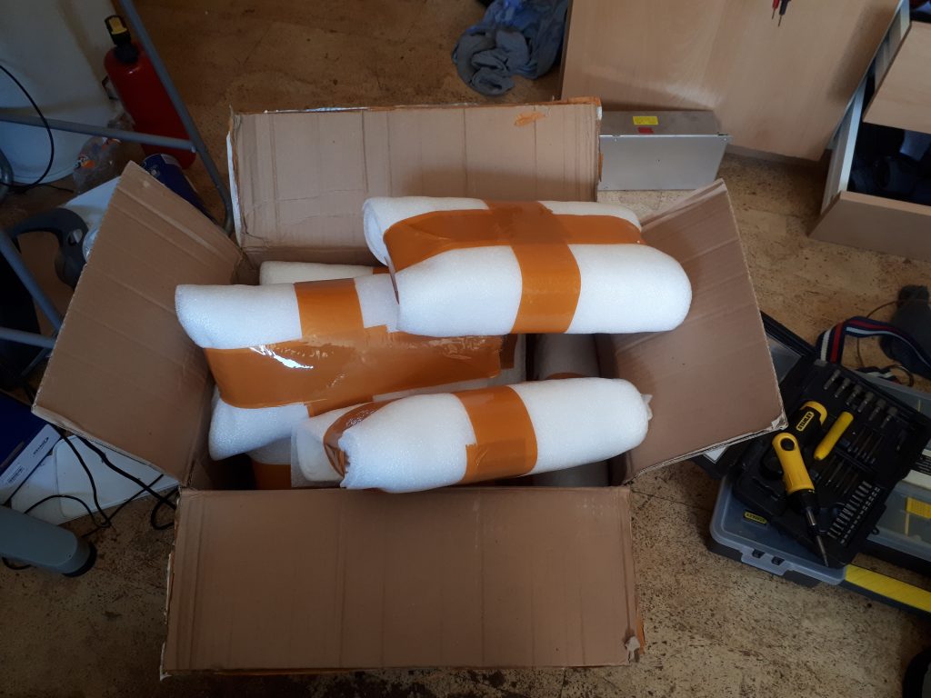
To store any excess energy produced a large lifepo4 battery is used.
why use a lifepo4 battery instead of li-ion or lead-acid for example?
lifepo4 is really great advantages compared to other kinds of batteries that make them excellent for a solar installation.
- long life (2000-5000 cycles)
- no maintenance
- very safe and stable
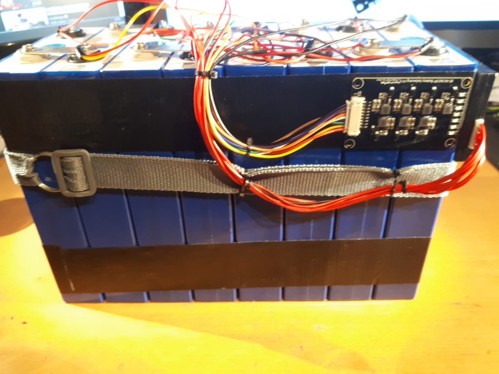
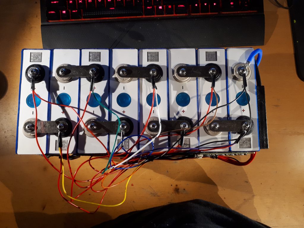
I went with 8 90Ah 3.2V cells for a theoretical maximum capacity of 2.3kwh with a voltage range of 24-28V
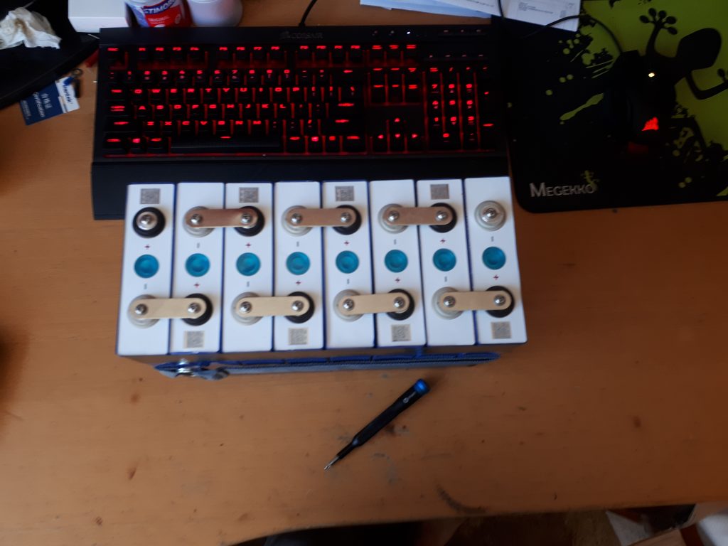
In practice I use 1.8-2kwh by not fully charging or discharging to increase the cycle life of them even more.
Here are the setting I use in the MPPT converter to charge the batteries:
- Charging limit voltage: 28.4V
- Equalize voltage: 28.2V
- Boost charging voltage: 28V
- Float Charging voltage: 27V
- Boost reconnect charging voltage: 26.6V
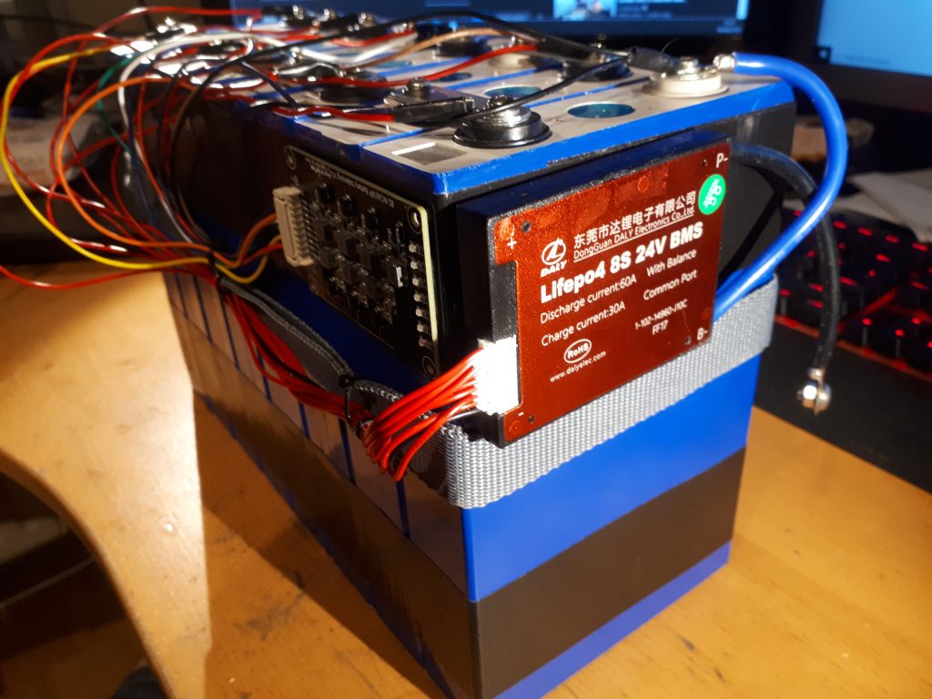
To protect the cells a BMS(battery management system) is used to fully disconnect the battery if one or more cells are at a dangerously low or high voltage, or if a short circuit or overcurrent situation occurs.
The maximum charge current is 30A to match the charge controller’s max current. The maximum discharge current is 60A to match the max continuous power of the inverter(1500W).
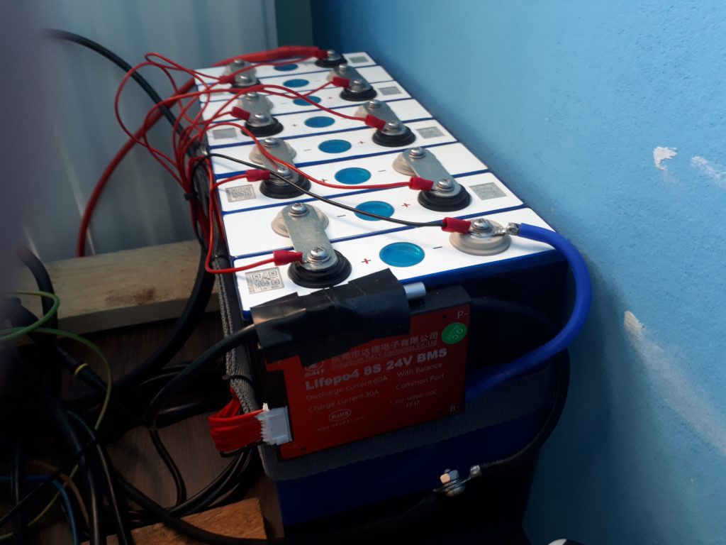
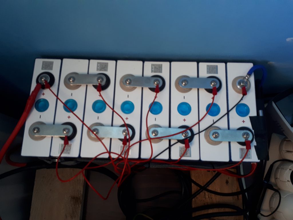
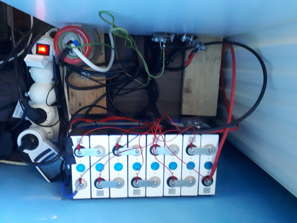
Because my cells were not that well balanced I had problems where the array was almost discharged or charged the voltage of the cells would drift far apart from each other. The BMS I use has the function to balance this out somewhat but the balance current (30mA) was way to low to make much of a difference. to solve this I use a dedicated balancer board that can balance the cells with a current up to 1.2A and will do so until they are withing 30mV of each other
Transfer switch
To switch between mains and the inverter I bought a dedicated transfer switch.
With a advertised max switching time of 16ms or less no electronic devices should shut down because of a small power loss. To test these claims I also hooked up my osciloscope to see how the transfer event hapens.
Nice