I’ve been working on building my own X-ray machine to image objects and determine their internal geometry without destructive testing. This project is still a work in progress, but I wanted to share some of my progress so far.
I’m using this post for my own documentation as well, so several sections remain incomplete. Parts of this project build on my previous Fusor project.
I’ve wanted to build an X-ray machine since finishing my Fusor in high school. In 2024, I was finally able to acquire some hard-to-find components and resume work on the project. My goal is to complete it this year.
X-Ray Tube
An X-ray tube works by generating an electron cloud in a vacuum using a filament, then accelerating these electrons to high speed toward an anode using high voltage. When the electrons strike the anode, approximately 1% of their energy is converted into X-rays, while the remaining 99% is converted into heat.
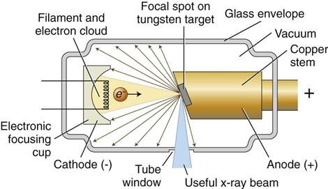
I selected the HBJ21 tube primarily due to its low cost and availability for import into Belgium. I attempted to source other tubes with better specifications and documentation, but was unable to secure shipping to my location.
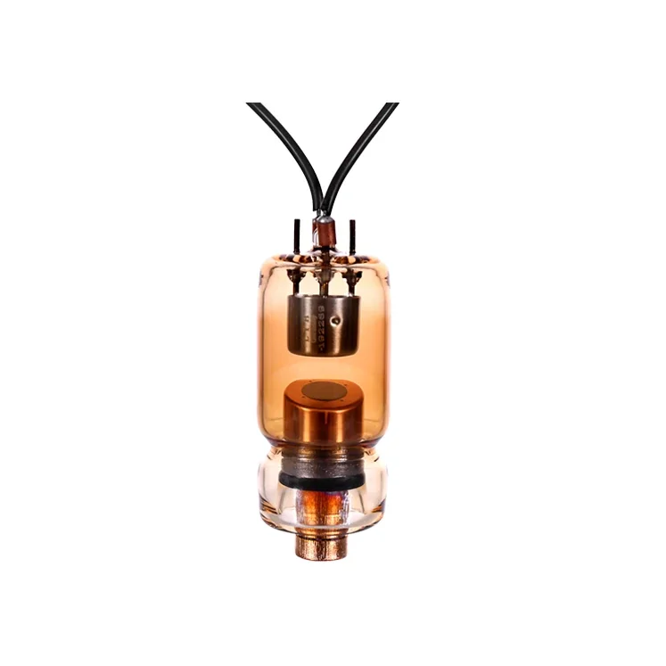
HBJ21 Specifications:
- Maximum X-ray tube voltage: 70 kV max (1.4 kW @ 20 mA)
- Minimum X-ray tube voltage: 50 kV min (1.0 kW @ 20 mA)
- Maximum X-ray tube current: 20 mA max
- Anode heat content: 7,000 J
- Max anode heat dissipation: 210 W
- Nominal focal spot value: 0.7 mm
- Maximum filament current: 2.9 A
- Target angle: 16°
- Price: €145
Beyond the listed specifications, no detailed documentation is available for this tube. This required me to calculate key values and create reference graphs myself. The most critical calculation is determining the maximum operating (exposure) time without burning out the tungsten anode.
The basic formula for calculating maximum exposure time is dividing the heat capacity by the applied power:
t = 7,000 / P
Below is a table showing the maximum exposure times at various voltage and current levels:
| Voltage (kV) | Current (mA) | Power (W) | Time to 7,000 J (s) | Continuous Operation? |
|---|---|---|---|---|
| 50 | 5 | 250 | 28.0 | ❌ |
| 50 | 10 | 500 | 14.0 | ❌ |
| 50 | 15 | 750 | 9.3 | ❌ |
| 50 | 20 | 1,000 | 7.0 | ❌ |
| 60 | 5 | 300 | 23.3 | ❌ |
| 60 | 10 | 600 | 11.7 | ❌ |
| 60 | 15 | 900 | 7.8 | ❌ |
| 60 | 20 | 1,200 | 5.8 | ❌ |
| 70 | 5 | 350 | 20.0 | ❌ |
| 70 | 10 | 700 | 10.0 | ❌ |
| 70 | 15 | 1,050 | 6.7 | ❌ |
| 70 | 20 | 1,400 | 5.0 | ❌ |
| Any | ≤3 | ≤210 | ∞ | ✅ |
Note: This calculation does not account for heat dissipation during exposure, so actual maximum exposure times will be longer. While the rated anode heat dissipation is 210 W, this is only achievable when operating near maximum temperature with adequate cooling. To be conservative, I assume the worst-case scenario with no active heat dissipation during exposure.
Radiation
An X-ray machine obviously produces dangerous levels of ionizing radiation that must be properly managed.
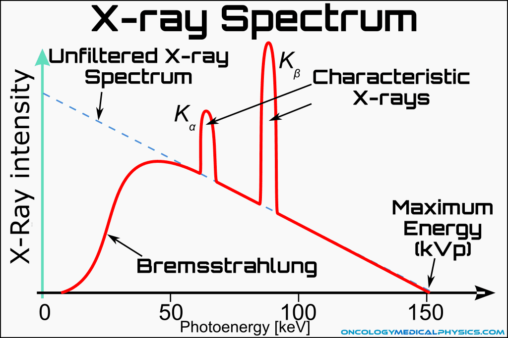
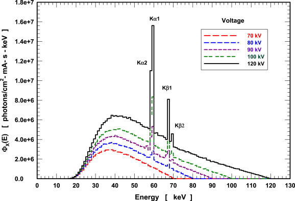
The tube actually generates a spectrum of X-rays rather than a single energy level. Low-energy photons must be filtered out, as they contribute little to image quality while posing unnecessary risk to living tissue. A broad spectrum from 20–70 keV (depending on tube voltage) is produced by Bremsstrahlung radiation. Additionally, the tungsten target produces two characteristic peaks at 59.3 keV and 67.2 keV.
Radiation Detection
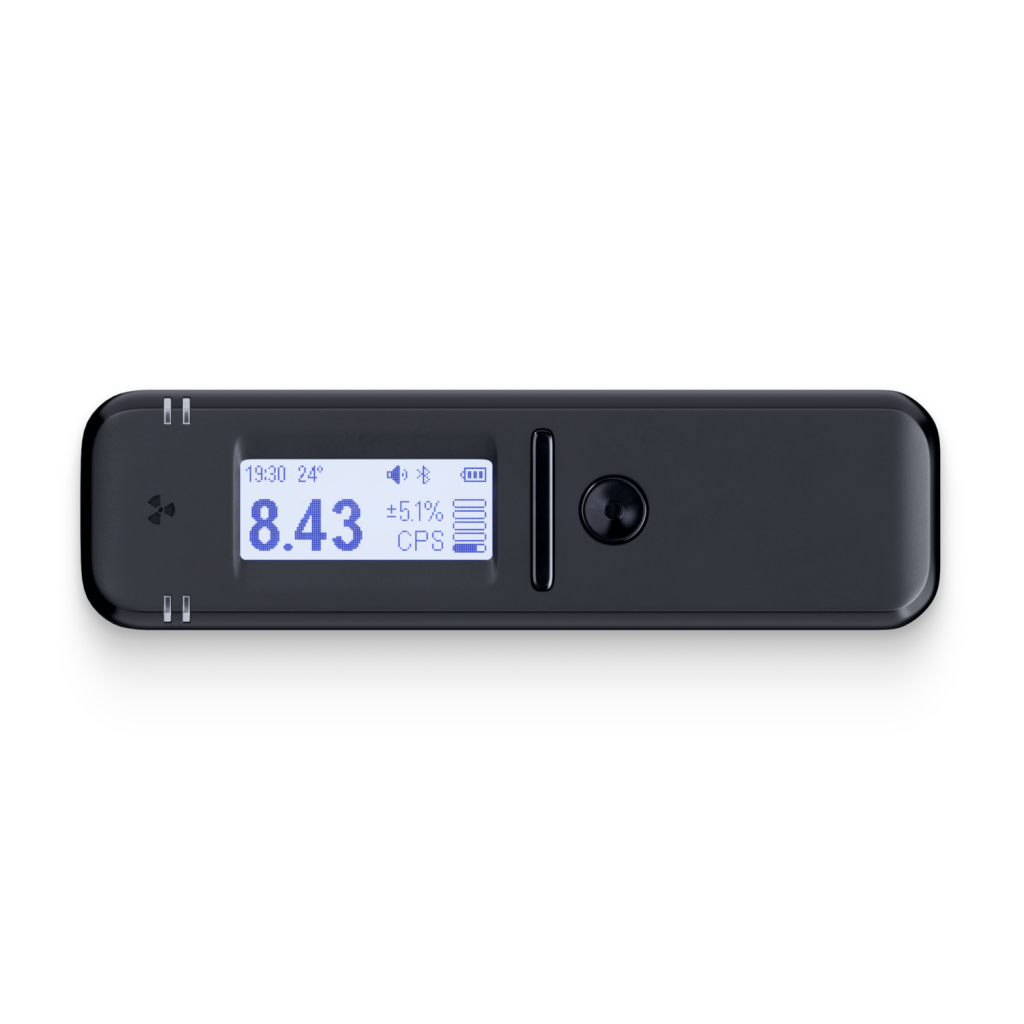
To detect radiation and measure the output spectrum, I use a Radiacode 103—a pocket-sized Bluetooth gamma spectrometer capable of measuring X-rays and gamma rays from 20 keV up to 3 MeV, with a maximum measurable radiation intensity of 1 mSv/h.
Radiation Shielding
Work in progress—this section will be updated with shielding design details and calculations.
High Voltage
Operating an X-ray tube requires very high voltages. For the HBJ21 tube, I need 50–70 kV. I split this requirement into a two-stage design:
- Stage 1: A high-voltage transformer generating up to 28 kVAC (40 kV peak)
- Stage 2: A voltage multiplier that steps this up to a maximum of 160 kVDC

High Voltage Transformer
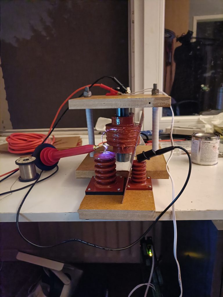
The high-voltage transformer generates the first stage output of up to 28 kVAC. It operates at high frequency to improve efficiency and reduce output ripple after rectification. My target frequency is 10 kHz, though 2 kHz should be the minimum for acceptable performance with the current component selection.
Transformer Core
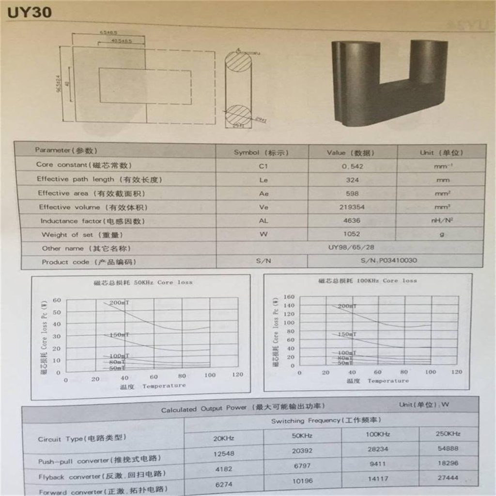
I selected the UY30 core from an AliExpress seller, primarily due to its large size which allows for well-spaced windings and a high primary-to-secondary turns ratio. I plan to operate this core at less than 10% of its rated power, so I’m not concerned about reaching any thermal or magnetic limits.
Transformer Windings & Insulation
High voltage insulation is critical for safety and reliability. Key lessons learned during winding construction:
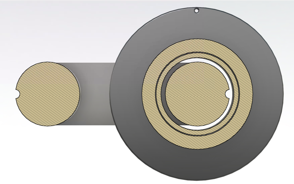
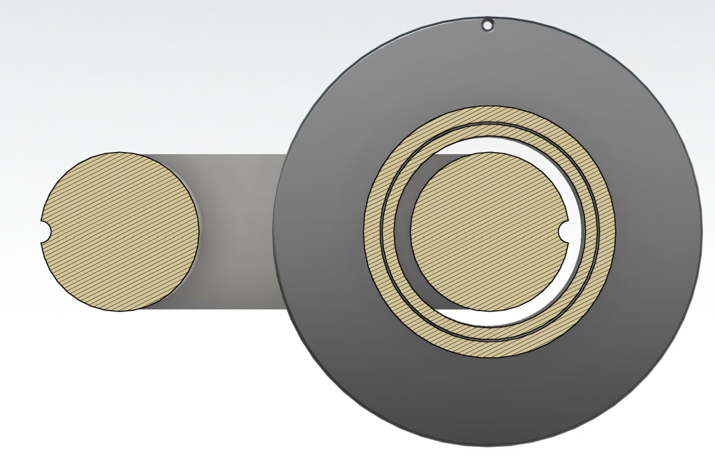
- Insulation materials: PETG, high-voltage varnish, and Teflon tape
- Varnish as adhesive: Used high-voltage varnish to bond components together
- 3D printed parts: Do not trust 3D-printed parts alone due to layer gaps; use varnish to fill these gaps completely
- Wire coating: Apply varnish to wire while coiling to prevent arcing between inner and outer layers through air gaps between wires
Varnish Selection
To protect and insulate the windings from damage and high voltage stress, I applied a thick coating of specialized high-voltage varnish. While many DIY builders use simpler solutions like nail polish or epoxy, the best solution I found is MG Chemicals 4228A liquid.
The difference in dielectric strength is significant:
- Epoxy: ~500 V/mil
- MG Chemicals 4228A: 3,700 V/mil
While it’s somewhat more expensive, the performance improvement justifies the cost. It’s also easy to apply, and the red coloring makes it simple to verify even coverage.
[Reference: MG Chemicals 4228A Technical Data Sheet]
Electronics
High Voltage Measurements
Work in progress—this section will detail the high voltage measurement and monitoring circuitry.
Filament Driver
The X-ray tube filament requires current control from 0 to 2.9 A. The filament current directly controls the number of electrons emitted, which in turn determines the X-ray output intensity.
Because the filament also serves as the return path for the high voltage generator through the X-ray tube, one side must always be connected directly to ground. This necessitates the use of high-side switching and current control.
Circuit design:
- An LM338T regulator provides a hard current limit of 2.82 A, preventing any over-current conditions
- A shunt resistor provides feedback for current limiting, variable current control, and ADC monitoring
- A MOSFET operating in its linear region enables variable current control
- A DAC provides the setpoint, while an op-amp adjusts the MOSFET to match the target current
This linear approach is not power-efficient and will dissipate several watts as heat, requiring adequate cooling. However, efficiency isn’t a primary concern here—I prioritized a simple, robust design over a more complex switching converter, which would introduce additional points of failure.
Hardware Safety Triggers
As a fallback for software-based safety systems, I implemented a hardware-based safety circuit that can independently disengage the high-voltage system and trigger an alarm if any parameter exceeds safe thresholds.
To maximize reliability, this safety system is kept as simple as possible. Multiple comparators monitor voltage readings from different system measurements. Each comparator’s trigger threshold is adjustable via trimmer potentiometers.
Operation:
- When a comparator is triggered (input exceeds threshold), it stops pulling down its output
- Because this condition only persists while the signal remains above threshold, a NOR SR latch circuit holds the alarm active until manually reset
- While the alarm is active: a buzzer sounds and a red LED indicates which measurement triggered the safety
- Multiple systems are simultaneously powered down to ensure a safe state:
- Power to the primary side of the high-voltage transformer
- DAC signal to the high-voltage transformer amplifier
- AC power to the high-voltage transformer amplifier
- Filament current driver
A self-test system using relays on each channel allows the safety system to be tested by ramping up the DAC signal and verifying that the safety circuit activates at the correct threshold.
Here is the complete safety circuit diagram:
[Insert safety circuit diagram]
Categories: Uncategorized
I like whatever part of the spectrum you’re on.
Hoe legaal is dees op een schaal van 0 tot nie echt?
Mvg